Introduction
Adhesive bonding in aerospace CFRP structures carries no margin for error. Bond failures in primary structures — fuselage panels, wing ribs, control surfaces — can be catastrophic, and surface preparation is the single variable that most determines whether a bond joint survives in service or fails at the interface.
What makes CFRP particularly demanding is a combination of factors that metals don't share: low surface energy from the resin matrix, mold release agent residues embedded during fabrication, and resin-rich surface layers that resist adhesive wetting. These aren't edge cases — they're the baseline condition of every CFRP part that comes off a tool.
Addressing these challenges starts with knowing which preparation methods work, when to use them, and what can go wrong. This article covers:
- Mechanical, chemical, and physical surface preparation approaches
- Method selection criteria for different CFRP applications
- Common failure modes tied to inadequate preparation
- Quality verification steps before bond application
TL;DR
- Untreated CFRP bonds fail early — low surface energy blocks adhesive wetting and contaminants create weak boundary layers
- Plasma treatment produces the strongest documented strength improvement: lap shear strength rising from 8.6 MPa to 31.6 MPa in published CFRP research
- Peel ply chemistry matters as much as technique — the wrong choice can cut fracture energy by over 90%
- Thermoset CFRP suits mechanical prep and solvent wipe; thermoplastic CFRP (PEEK, PEKK) needs plasma or chemical activation
- For airworthiness compliance, process documentation and traceability are as critical as the prep method
Why Surface Preparation Is Critical for CFRP Adhesive Bonding
The Surface Chemistry Problem
CFRP laminates emerge from the mold with low surface energy. Without treatment, adhesives cannot spread and wet the surface effectively. They bead rather than flow, leaving gaps, voids, and weak interfacial contact. The consequences show up directly in bond strength.
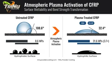
Published research on atmospheric pressure plasma treatment quantifies what "untreated vs. treated" actually means: lap shear strength rose from 8.6 MPa to 31.6 MPa, while water contact angle dropped from 108.6° to 32.4°, confirming a shift from hydrophobic to hydrophilic.
Contamination Sources
The most dangerous contaminants on CFRP surfaces are invisible:
- Mold release agents — silicone-based PDMS residues transfer from the tool to the laminate surface during cure; NASA Langley research identified PDMS as a primary weak-boundary-layer risk on CFRP
- Process oils and handling residues — introduced during trimming, drilling, or part handling after demolding
- Atmospheric contamination — moisture adsorption and airborne organics deposited between prep and bonding
Even trace siloxane transfer from a peel ply can reduce fracture energy from approximately 910 J/m² to 86 J/m² — a collapse in bond toughness caused entirely by surface chemistry, not adhesive or laminate quality.
Failure Mode Distinction
Per ASTM D5573, which governs failure mode classification in adhesively bonded fiber-reinforced plastic joints:
| Failure Mode | Location | Interpretation |
|---|---|---|
| Cohesive failure | Within the adhesive layer | Interface exceeded — acceptable |
| Adhesive/interfacial failure | At the CFRP-adhesive interface | Surface prep inadequate — unacceptable |
| Fiber-tear failure | Within the composite near-surface | Strong bond — generally desirable |
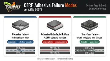
Poor surface preparation almost always produces adhesive failure. The adhesive cured correctly; it simply never bonded to the substrate.
Qualification and Traceability Requirements
FAA/JAMS bond qualification guidance frames a qualified bonding system as the combination of adhesive, substrate, surface preparation, and bonding process, documented together. Each variable in the process must be captured for traceability:
- Solvent type and wipe medium
- Number of passes and wipe direction
- Environmental conditions at time of prep
- Elapsed time between preparation and bonding
Traceability isn't a paperwork formality. It's how bonded structures earn airworthiness compliance.
Mechanical Surface Preparation Methods for CFRP
Peel Ply
Peel ply is a sacrificial woven fabric co-cured onto the CFRP laminate surface. Removed immediately before bonding, it exposes a clean, textured, chemically active resin surface without requiring subsequent abrasion.
Two variants exist, and the difference matters:
- Dry peel ply — woven fabric without resin pre-impregnation; produces a textured surface with mechanical interlocking potential; NASA/NIA testing recorded dry polyester peel ply at 28.0 MPa apparent shear strength
- Wet (pre-impregnated) peel ply — pre-wetted with compatible resin during layup; minimizes dry fiber residue and produces more uniform surface energy, though NASA data showed wet peel ply at 25.5 MPa with 95% adhesive failure — a result tied to specific adhesive/peel ply incompatibility
Critical caveat: peel ply chemistry is not interchangeable. AMTAS/NIAR research on Boeing 777 and 787 bonding found that "Super Release Blue" peel plies with siloxane coatings transferred contamination to the laminate surface, dramatically reducing fracture energy. Always qualify the specific peel ply product and adhesive combination, not just the fiber family.
Abrasive Sanding
Manual abrasion with silicon carbide paper increases surface roughness and mechanical interlocking area. The primary risk is fiber damage — over-sanding severs surface fibers, creating stress concentrations that become crack initiation sites under load. Grit selection matters: 80–120 grit is typically appropriate for surface activation without cutting into the fiber layer.
Grit Blasting
Grit blasting delivers more uniform and controlled mechanical abrasion than hand sanding across large surface areas. Propelling abrasive media (aluminum oxide, glass bead, or silicon carbide) at regulated pressure produces consistent surface topography — important for production environments where repeatability drives bond quality.
NASA/NIA aerospace CFRP testing used 220-grit silicon carbide at 80 psi as a benchmark. Two risks require specific process controls:
- Media embedment — alumina particles can become lodged in surface fibers, particularly on thermoplastic CFRP, creating contaminant sites that undermine bond performance
- Fiber damage — excessive pressure or aggressive media can cut surface fibers, weakening the bond substrate rather than preparing it
Both risks are controlled through the same lever: establishing blasting parameters per part material and condition, then holding to them — not applying uniform settings regardless of substrate.
Solvent Wipe as Mandatory Follow-Up
Mechanical abrasion alone is never the final step. A post-blast solvent wipe removes loose particles, abraded debris, and surface oils before adhesive application. The standard protocol is a two-wipe method:
- Wet wipe — applies solvent (MEK, acetone, or IPA depending on resin system compatibility) and mobilizes contamination
- Dry wipe — removes mobilized contamination before the solvent evaporates and redeposits it
A single-wipe method redistributes contamination rather than removing it.
Chemical and Physical Surface Treatment Methods
Chemical Primers
After mechanical prep, adhesion-promoting primers — typically epoxy-based silane primers — bridge chemical incompatibilities between the CFRP surface and the adhesive system. They form covalent bonds to both surfaces, extending durability under humid or thermally cycled service conditions. Chromic acid etching, once used for aluminum-composite hybrid bonds, is being phased out due to environmental and health concerns.
Plasma Treatment
Atmospheric plasma treatment is the current preferred — and best-documented — physical activation method for aerospace CFRP. It works on three fronts at once:
- Removes organic surface contaminants
- Increases surface energy
- Introduces reactive functional groups (hydroxyl, carbonyl) that bond chemically with adhesive systems
The quantitative evidence is clear. Contact angle drops from 108.6° to 32.4°; lap shear strength more than triples. For CF/PEKK thermoplastic composites, a 2024 study found atmospheric plasma activation outperformed both peel ply and mechanical abrasion, improving tensile load-carrying performance by up to 5× versus untreated joints.
Two process constraints matter here. First, plasma activation is time-sensitive: treated surfaces undergo hydrophobic recovery, with surface energy degrading over hours to days as activated groups reorient. The maximum allowable time between plasma treatment and adhesive application is controlled by the governing process specification — treat it as a hard process window, not a guideline. Second, overtreatment carries its own risk. Research reports resin pyrolysis at surface temperatures above 175°C during plasma exposure; excessive treatment damages the matrix and weakens the bond substrate.
Laser Surface Treatment
Laser ablation is an emerging precision method capable of selectively removing surface layers with micron-level control. A frequency-tripled Nd:YAG laser at 355 nm, tested in NASA/NIA research, achieved a contact angle of less than 1° with optimized parameters — and apparent shear strength of 27.6 MPa, matching dry peel ply at 28.0 MPa. All laser-etched samples showed light fiber-tear failure modes, indicating strong interface performance.
The critical variable is parameter control. The same NASA study showed that a different laser setting produced hydrophobic surfaces near 100° contact angle — the laser can degrade wettability just as easily as it improves it if parameters are wrong. Laser prep is research-qualified evidence for aerospace applications, not yet a universally OEM-approved production process.
Thermoset vs. Thermoplastic CFRP: Key Differences in Surface Preparation
The matrix resin type fundamentally changes the prep approach required.
| Parameter | Thermoset CFRP (epoxy matrix) | Thermoplastic CFRP (PEEK, PEKK, PPS) |
|---|---|---|
| Baseline surface energy | Moderate — responds to mechanical prep | Very low (36–44 mJ/m² for PEEK) |
| Chemical inertness | Low — compatible with epoxy adhesives | High — resists solvents and standard abrasion |
| Adequate prep method | Peel ply + solvent wipe; abrasion + solvent wipe | Plasma activation or chemical etching required |
| Mechanical abrasion alone | Generally sufficient for secondary structures | Insufficient — does not activate surface |
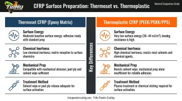
Thermoset CFRP epoxy surfaces are chemically compatible with epoxy adhesives. Mechanical prep creates enough surface area and energy for structural bonds in most applications — peel ply removal or abrasion combined with a solvent wipe is typically sufficient.
Thermoplastic CFRP behaves differently. PEEK and PEKK matrices are chemically inert by design — the same property that makes them heat-resistant and solvent-resistant makes them difficult to bond. Solvent cleaning does nothing. Mechanical abrasion increases roughness but doesn't activate the surface chemistry. Plasma treatment or chemical etching is required to introduce bondable functional groups.
That activation requirement has direct implications for production workflows. Aerospace programs are now qualifying thermoplastic composites for primary structures — fuselage panels, wing ribs, and structural sub-assemblies. GKN Fokker and Gulfstream have both assessed thermoplastic CFRP for primary applications. Plasma and activation-based prep protocols are moving from repair scenarios into production-line bonding processes as a result.
Quality Verification After Surface Preparation
Correct surface preparation only counts if it can be verified — and in aerospace bonding, that verification happens through a defined set of inspection methods before any adhesive is applied.
Contact Angle Measurement
Water contact angle on the prepared surface indicates surface energy. Research benchmarks include:
- Untreated CFRP: ~79–108° (hydrophobic, poor wetting)
- Plasma-treated CFRP: ~32° in published studies
- Laser-optimized CFRP: <1° in NASA testing
Lower angles confirm adequate surface energy for adhesive spreading. Contact angle measurement is non-destructive, making it a practical in-process quality gate before adhesive application. Note that specific pass/fail thresholds are defined by governing process specifications, not universal standards.
Contamination Detection
For CFRP-specific contamination verification, NASA Langley research validated LIBS (Laser-Induced Breakdown Spectroscopy) and OSEE (Optically Stimulated Electron Emission) as methods for detecting PDMS silicone contamination on CFRP surfaces. LIBS monitors the Si I emission line at 288.2 nm; OSEE measures photocurrent changes after laser surface treatment.
Process Traceability Documentation
Per FAA/JAMS guidance, every bonding process must document:
- Preparation method and materials used
- Solvent type, wipe medium, number of passes, and wipe direction
- Technician qualification
- Environmental conditions (temperature, humidity)
- Time elapsed between preparation and adhesive application
For structural bond certification, this documentation is required. It is the mechanism by which the preparation sequence is verified to have occurred correctly, and it is the basis for airworthiness compliance.
Best Practices for Selecting the Right Surface Prep Method
Decision Framework
| CFRP Type | Production Scale | Bond Criticality | Recommended Method |
|---|---|---|---|
| Thermoset epoxy | Manual/low volume | Secondary structure | Peel ply + solvent wipe |
| Thermoset epoxy | Production line | Primary structure | Peel ply + abrasion + solvent wipe + primer |
| Thermoplastic (PEEK/PEKK) | Any | Primary structure | Plasma treatment + primer + bond within process window |
| Either | Automated production | Primary structure | Laser ablation (research-qualified) or plasma + solvent wipe |
Process Sequence Discipline
Surface prep is never a single step. A typical aerospace bonding sequence looks like this:
- Peel ply removal — expose fresh resin surface immediately before prep
- Solvent wipe (wet) — mobilize surface contamination
- Solvent wipe (dry) — remove mobilized contamination
- Mechanical abrasion — controlled grit and technique
- Solvent wipe (wet + dry) — remove abrasion debris
- Primer application — adhesion promotion where required
- Bond within defined time window — elapsed time tracked and documented
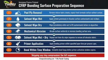
Skipping any step compromises the entire sequence. The prep method selection matters, but consistent execution of each step in the defined order is what produces repeatable structural bonds. When execution varies, bond quality varies — regardless of which method was chosen.
Frequently Asked Questions
Why is surface preparation important in adhesive bonding?
Surface prep removes contaminants, increases surface energy, and creates mechanical and chemical bonding sites. Without it, adhesives cannot wet and spread across the substrate, producing adhesive failure at the interface rather than the cohesive failure that indicates a sound bond.
What are the surface preparation techniques for adhesion to aerospace thermoplastic composites?
Atmospheric plasma treatment is the primary method — it activates the chemically inert surface and introduces reactive functional groups. UV/ozone treatment and chemical etching are alternatives. Mechanical abrasion alone is insufficient for PEEK or PEKK because it increases roughness without activating surface chemistry.
What adhesive is used for CFRP?
Epoxy-based film adhesives (covered under SAE AMS3695) are standard for large structural bonds in autoclave or out-of-autoclave cycles. Structural paste adhesives handle smaller bonds, repairs, and gap-filling. Both must be qualified alongside the surface preparation method as a system.
What is peel ply and how does it simplify CFRP surface preparation?
Peel ply is a sacrificial woven fabric co-cured onto the CFRP laminate. Removing it immediately before bonding exposes a clean, textured surface — eliminating sanding and producing more uniform surface energy than manual abrasion. The specific product must be qualified with the adhesive system, since chemistry mismatches can contaminate the bond surface.
How do you verify that a CFRP surface is ready for bonding?
Contact angle measurement confirms surface energy; LIBS and OSEE testing detect silicone contamination. The full prep sequence — method, materials, conditions, and elapsed time — must be documented per the governing process specification before bonding proceeds.